- September 12, 2009
- 798
- 577
- Home Country
-
 Germany
Hi,
I would like to showcase a project of mine, that I have been working on for quite some time.
What is it?
AtmoOrb is a lamp similar to the very popular Philips Hue lights. Like the original you can control the color of this lamp via wifi and make your living room more colorful.

So, why not just use the original?
During the implementation for Hue support in AtmoLight to use them as ambilight controlled by MediaPortal, @Rick164 came across some of its limitations. Mainly the fact that there is a considerable delay between sending a new color and actually seeing that color displayed. Sometimes this delay can be up to 3 seconds, which of course is quite high. The fact that these lamps cost a lot of money also did not speak in their favour. With 30€ for one bulb (without the bridge) or 130€ for a starter kit, these things are expensive.
Early on @Rick164 and I thought there must be a better solution. However it seems that the competition has similar limitations aswell. So the idea to build this ourself came up, but not until I saw a video of a new and cheap wifi module did we actually start on building it.
Planning the Orb.
When we first thought about building our own lamp we already knew we wanted to use an Arduino and WS2812B leds, which we both were familiar with from "normal" ambilight systems. But the problem was always, how do we send data to the Arduino? Because we did not want to attach a 10m USB cable. There are of course wifi modules/shields for Arduinos, but they cost a lot of money, and the idea was to be cheaper than the original. One day I saw a video about this new wifi module from China called ESP8266, you can connect to it via UART and it only cost 5€. And it seemed to be very easy to use it with an Arduino. So, I started planning.
The idea was to use a very small Arduino, and a cheap one. So one of these Arduino clones would do. I decided I wanted to use a Micro Pro clone. Hardware wise its very similar to the original Arduino Leonardo, just smaller. It has two serial ports, which makes it perfect. One would be used by the USB connection to my pc for debugging and the other one could be used by the ESP8266. And with around 7€ its also cheap.
Because the ESP8266 works with 3.3V and the Arduino and leds work with 5V, I also needed a voltage regulator to power the ESP8266 and some resistors to build a voltage divider for the receiving pin of the ESP8266. Some capacitors to stabilize the voltage, and we are good.
For the power supply I had some old 5V supplies laying around, so one of those would do.
Next step, making a schematic and drawing a board layout, so we would know how big of a board we need and where to solder what part later on. Using the software Eagle, I came up with this.

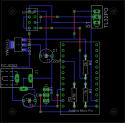
But wait, don't we want to put all that stuff in a nice lamp? Sure we do. Again, I wanted something nice and cheap, so, where do we get something like that? Right, at IKEA. I choose the IKEA Fado, a bulb out of white glass, which would diffuse the light nicely and for 10€ its a steal.
The parts.
- Arduino Micro Pro 8€
- ESP8266 5€
- 27x WS2812B pixel 11€
- 5V 4A power supply 10€
- IKEA Fado 10€
- AMS1117 3.3V regulator 0.10€
- Perfboard 1€
- 2k Ohm resistor 0.10€
- 1k Ohm resistor 0.10€
- 470 Ohm resistor 0.10€
- 22uF capacitor 0.20€
- 1000uF capacitor 0.40€
- Flip switch 1€
- Power jack 1€
- Jumper wire 1€
- Pin and pin header 1€
Total: 50€
Please keep in mind I had power supply, perfboard, resistors, capacitors, flip switch, power jack and jumper wire laying around and had not to buy those. Also some of these prices are estimates and from the cheapest place I could find (China).
Proof of concept and first tests.
Before soldering everything together its better to test if everything is actually working like it should. So I hooked everything up to a breadboard and started programming the Arduino to see if I would be able to log into my wifi and if I could receive data quickly enough and without errors. While I was able to log into my wifi without any problems I did have some at receiving data. But the problem did not lay in the ESP8266, but rather my crappy router that has a very weak wifi signal. Using a wifi extender these problems were gone quickly.

In my testing setup you can see the "Arduino" Micro Pro in the middle and the ESP8266 hanging on the left. Hanging in the middle is a small board for the 3.3V regulator, which sat on the back. Also visible the 3 resistors I use to regulate the voltage of the receiving line of the ESP8266. As I did not have a 2k Ohm resistor, I used 2 1k Ohm, which amounts to the same.
Soldering the board.
Because I took the time to make a board layout, this was very easy and quickly done. I had a plan where everything went and when I wasn't sure anymore, I could just check.
The board from the front after the first soldering session.

And from the back.

I later decided I also wanted to add a flip switch to switch one of the ESP8266 pins to ground. This would allow me to flash the ESP8266 with a new firmware without much trouble. After everything was finished I also decided to add a 433MHz rf transmitter that would be able to control the rf power socket the lamp is using to save some energy. The rf transmitter would turn off the power socket after 15 minutes in idle. But this of course is optional. So the final version from the front and back look like this.


The board itself is 5cm by 5cm. So very small. And therefore I am able to fit it in the bottom of the lamp base.

I decided to use WS2812B pixels instead of strips, to get as many leds in the lamp as possible. They come like this.

Some graphics I made to see how to arrange different leds types to get the best result. With led strips.
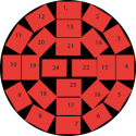
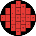
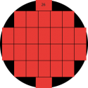
And for the pixels.
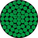
The pixels themselves are not connected and you can just break them apart. Because of this I had some fun times (not really) soldering these together.


Finally done with them, I used hot glue to fix them to the top of the lamp base and connected them up to the board.


Putting the bulb on top and it looks like, well like a normal Fado lamp .
.

What about the Arduino sketch?
Working with the ESP8266 is very easy. It uses AT commands, so if I want to change a setting in the ESP8266 I can just send one of these commands via UART to the module and it will respond via UART to me. With the framework for the communication out of the way @Rick164 and I decided on a set of commands we wanted to use. For example, to change the color to red we have to send "setcolor:FF0000;" to our lamp. Implementing this was quite easy. The harder part was to add some kind of smoothing. If we send 60 setcolor commands a second, it can get very hectic, even without sending lots of commands we wanted to have a nice transition between two colors. After a lot of testing different solutions, we came up with a system that looks like this.

The Arduino will try to change the color within 50ms, if during this process we get a new setcolor command we start from that point and smooth to the new color. This is how it looks with smaller color changes.

And this is how it would look like if the smoothing process does not get interrupted by a new color.

The length and the frequency of the smoothing can be adjusted in the Arduino sketch. Apart from this I am using the FastLED library to drive the leds. If you want to check out the code for yourself, head over to our GitHub repository.
https://github.com/ambilight-4-mediaportal/AtmoOrb
So what now?
The idea from the beginning of course was to let AtmoLight control the light. So I implemented a AtmoOrb target into AtmoLight, with the recent rework @Rick164 and I have done to AtmoLight this was very easy. The AtmoOrb handler has been added with the idea in mind to add as many of these lamps to your home as you want. So driving multiple lamps at the same time is no problem. I also added the possibility to scan a different area of the screen for each lamp. So e.g. one lamp is on the left of your screen and one is on the right, then AtmoLight is able to send only the color from the left part of the screen to the left lamp and only the right part of the screen to the right lamp. All of this is configurable from the AtmoLight setup form.

How does it look?
Here a small video showing off this system.
And some music with the VUMeter effect enabled (please crank up your speakers)
That sound complicated, is there another/easier way?
@Rick164 has also been working on such a lamp. He has been testing and working with different Arduinos and wifi modules for some time now and will probably have a post like this soon aswell. His approach is a bit more user friendly, with solutions that don't require that much tinkering but may cost a little bit more.
Interested in the Arduino source code or the Eagle files?
No problem, everything is open source. You can find everything you need in our GitHub repository.
https://github.com/ambilight-4-mediaportal/AtmoOrb
I would like to showcase a project of mine, that I have been working on for quite some time.
What is it?
AtmoOrb is a lamp similar to the very popular Philips Hue lights. Like the original you can control the color of this lamp via wifi and make your living room more colorful.

So, why not just use the original?
During the implementation for Hue support in AtmoLight to use them as ambilight controlled by MediaPortal, @Rick164 came across some of its limitations. Mainly the fact that there is a considerable delay between sending a new color and actually seeing that color displayed. Sometimes this delay can be up to 3 seconds, which of course is quite high. The fact that these lamps cost a lot of money also did not speak in their favour. With 30€ for one bulb (without the bridge) or 130€ for a starter kit, these things are expensive.
Early on @Rick164 and I thought there must be a better solution. However it seems that the competition has similar limitations aswell. So the idea to build this ourself came up, but not until I saw a video of a new and cheap wifi module did we actually start on building it.
Planning the Orb.
When we first thought about building our own lamp we already knew we wanted to use an Arduino and WS2812B leds, which we both were familiar with from "normal" ambilight systems. But the problem was always, how do we send data to the Arduino? Because we did not want to attach a 10m USB cable. There are of course wifi modules/shields for Arduinos, but they cost a lot of money, and the idea was to be cheaper than the original. One day I saw a video about this new wifi module from China called ESP8266, you can connect to it via UART and it only cost 5€. And it seemed to be very easy to use it with an Arduino. So, I started planning.
The idea was to use a very small Arduino, and a cheap one. So one of these Arduino clones would do. I decided I wanted to use a Micro Pro clone. Hardware wise its very similar to the original Arduino Leonardo, just smaller. It has two serial ports, which makes it perfect. One would be used by the USB connection to my pc for debugging and the other one could be used by the ESP8266. And with around 7€ its also cheap.
Because the ESP8266 works with 3.3V and the Arduino and leds work with 5V, I also needed a voltage regulator to power the ESP8266 and some resistors to build a voltage divider for the receiving pin of the ESP8266. Some capacitors to stabilize the voltage, and we are good.
For the power supply I had some old 5V supplies laying around, so one of those would do.
Next step, making a schematic and drawing a board layout, so we would know how big of a board we need and where to solder what part later on. Using the software Eagle, I came up with this.


But wait, don't we want to put all that stuff in a nice lamp? Sure we do. Again, I wanted something nice and cheap, so, where do we get something like that? Right, at IKEA. I choose the IKEA Fado, a bulb out of white glass, which would diffuse the light nicely and for 10€ its a steal.
The parts.
- Arduino Micro Pro 8€
- ESP8266 5€
- 27x WS2812B pixel 11€
- 5V 4A power supply 10€
- IKEA Fado 10€
- AMS1117 3.3V regulator 0.10€
- Perfboard 1€
- 2k Ohm resistor 0.10€
- 1k Ohm resistor 0.10€
- 470 Ohm resistor 0.10€
- 22uF capacitor 0.20€
- 1000uF capacitor 0.40€
- Flip switch 1€
- Power jack 1€
- Jumper wire 1€
- Pin and pin header 1€
Total: 50€
Please keep in mind I had power supply, perfboard, resistors, capacitors, flip switch, power jack and jumper wire laying around and had not to buy those. Also some of these prices are estimates and from the cheapest place I could find (China).
Proof of concept and first tests.
Before soldering everything together its better to test if everything is actually working like it should. So I hooked everything up to a breadboard and started programming the Arduino to see if I would be able to log into my wifi and if I could receive data quickly enough and without errors. While I was able to log into my wifi without any problems I did have some at receiving data. But the problem did not lay in the ESP8266, but rather my crappy router that has a very weak wifi signal. Using a wifi extender these problems were gone quickly.

In my testing setup you can see the "Arduino" Micro Pro in the middle and the ESP8266 hanging on the left. Hanging in the middle is a small board for the 3.3V regulator, which sat on the back. Also visible the 3 resistors I use to regulate the voltage of the receiving line of the ESP8266. As I did not have a 2k Ohm resistor, I used 2 1k Ohm, which amounts to the same.
Soldering the board.
Because I took the time to make a board layout, this was very easy and quickly done. I had a plan where everything went and when I wasn't sure anymore, I could just check.
The board from the front after the first soldering session.

And from the back.

I later decided I also wanted to add a flip switch to switch one of the ESP8266 pins to ground. This would allow me to flash the ESP8266 with a new firmware without much trouble. After everything was finished I also decided to add a 433MHz rf transmitter that would be able to control the rf power socket the lamp is using to save some energy. The rf transmitter would turn off the power socket after 15 minutes in idle. But this of course is optional. So the final version from the front and back look like this.


The board itself is 5cm by 5cm. So very small. And therefore I am able to fit it in the bottom of the lamp base.

I decided to use WS2812B pixels instead of strips, to get as many leds in the lamp as possible. They come like this.

Some graphics I made to see how to arrange different leds types to get the best result. With led strips.


And for the pixels.

The pixels themselves are not connected and you can just break them apart. Because of this I had some fun times (not really) soldering these together.


Finally done with them, I used hot glue to fix them to the top of the lamp base and connected them up to the board.


Putting the bulb on top and it looks like, well like a normal Fado lamp

What about the Arduino sketch?
Working with the ESP8266 is very easy. It uses AT commands, so if I want to change a setting in the ESP8266 I can just send one of these commands via UART to the module and it will respond via UART to me. With the framework for the communication out of the way @Rick164 and I decided on a set of commands we wanted to use. For example, to change the color to red we have to send "setcolor:FF0000;" to our lamp. Implementing this was quite easy. The harder part was to add some kind of smoothing. If we send 60 setcolor commands a second, it can get very hectic, even without sending lots of commands we wanted to have a nice transition between two colors. After a lot of testing different solutions, we came up with a system that looks like this.

The Arduino will try to change the color within 50ms, if during this process we get a new setcolor command we start from that point and smooth to the new color. This is how it looks with smaller color changes.

And this is how it would look like if the smoothing process does not get interrupted by a new color.

The length and the frequency of the smoothing can be adjusted in the Arduino sketch. Apart from this I am using the FastLED library to drive the leds. If you want to check out the code for yourself, head over to our GitHub repository.
https://github.com/ambilight-4-mediaportal/AtmoOrb
So what now?
The idea from the beginning of course was to let AtmoLight control the light. So I implemented a AtmoOrb target into AtmoLight, with the recent rework @Rick164 and I have done to AtmoLight this was very easy. The AtmoOrb handler has been added with the idea in mind to add as many of these lamps to your home as you want. So driving multiple lamps at the same time is no problem. I also added the possibility to scan a different area of the screen for each lamp. So e.g. one lamp is on the left of your screen and one is on the right, then AtmoLight is able to send only the color from the left part of the screen to the left lamp and only the right part of the screen to the right lamp. All of this is configurable from the AtmoLight setup form.

How does it look?
Here a small video showing off this system.
And some music with the VUMeter effect enabled (please crank up your speakers)
That sound complicated, is there another/easier way?
@Rick164 has also been working on such a lamp. He has been testing and working with different Arduinos and wifi modules for some time now and will probably have a post like this soon aswell. His approach is a bit more user friendly, with solutions that don't require that much tinkering but may cost a little bit more.
Interested in the Arduino source code or the Eagle files?
No problem, everything is open source. You can find everything you need in our GitHub repository.
https://github.com/ambilight-4-mediaportal/AtmoOrb
Last edited:
